
Flexible Buried Bridges: Design and Construction (Part 2)
Article provided by the Contech Engineered Solutions as seen in the December 2021 issue of Informed Infrastructure Magazine. Click here to access the full article and take the PDH quiz with AIA LU/PDH credit in all states.
This is part 2 of a two part series (read part 1 – Flexible Buried Steel Bridges: Advantages and Applications)
Evaluate Siting Conditions and Feasibility
The first step in developing a buried bridge alternative is to determine if site geometric limitations will allow a buried bridge structure to fit at the desired location.
To evaluate this, it is critical to determine how large the structure needs to be and how much room is available.
- For hydraulic applications, the structure size typically is determined by a hydraulic analysis that establishes a minimum inside end area or span based on the water course passing through it.
- For non-hydraulic applications, the minimum structure size usually is determined based on inside clearance requirements.
Maximum structure size limitations often are governed by the available vertical distance from the bottom of the structure to the top of the road grade passing over the structure as well as minimum soil cover needed to meet design requirements.
- Other factors that limit structure size may include:
- Minimum depth of soil cover needed for utilities crossing over the structure
- Presence of existing bridge elements (for in-place bridge replacement applications)
- Right-of-way boundaries
- Foundation depth
- Other project-specific geometric limitations
As a rule of thumb, the maximum span-to-rise ratio for a flexible buried bridge is on the order of 4:1 to 5:1, depending on the structure span and shape. It is important to recognize that a buried bridge alternative will rarely have the same span as the conventional bridge option. This can help reduce the footprint of the project. Figure 5 illustrates basic information that should be considered when evaluating geometric feasibility.

Figure 5. Basic information that should be considered when evaluating geometric feasibility.
Engineers often approach a crossing by considering how long of a span is required to cross from “bank to bank.” However, many engineers have found that by reorienting the challenge to consider how large of an opening is required to pass the hydraulics or capture the clearance box can require a much smaller opening and span.
Figure 5 effectively demonstrates how a buried bridge using a much smaller span and footprint can achieve the project objectives. This will typically result in a more cost-effective solution as well.
After feasibility of a buried bridge alternative is determined, the next step is to consider structure geometry options. At this point, the project engineer should reach out to a manufacturer to evaluate the best shape to use as a starting point for a design evaluation.
Most structure manufacturers will have a library of “standard” shapes that can be used as a starting point, and one of these may be a perfect fit for what is needed. If not, a custom geometry can be developed that is optimized for the project requirements.
Basic Design Inputs
Buried bridge structures are designed in accordance with Section 12 of the AASHTO LRFD Bridge Design Specifications. The structure design evaluation will involve several basic inputs. Deep-corrugated buried bridge structures (corrugation depth >5”) are analyzed using finite-element analysis (FEA).
In addition to the structure geometry and material properties, the FEA requires inputs for foundation soil properties, engineered backfill materials (placed around the structure), and site soil properties outside of the engineered backfill materials. The engineered backfill material is specified by the structure designer based on AASHTO requirements and the FEA results.
Foundation soil and site soil properties used for FEA inputs can usually be determined based on information provided in soil boring logs, test pit data and other information available regarding site conditions.
If project soil information is limited or not available, reasonable assumptions can be made. When they are necessary, the assumptions should be clearly stated by the structure designer and acknowledged by the project engineer or owner. At this stage, assumptions may result in a conservative design. It would be in the owner’s best interest to obtain the needed soil information prior to final design to confirm the initial assumptions.

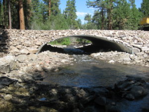
Figure 6a. Before a bridge replacement with custom geometry. (Vermont Agency of Transportation; St. Johnsbury, Vt.)

Figure 6b. After a bridge replacement with custom geometry. (Vermont Agency of Transportation; St. Johnsbury, Vt.)
Backfill Considerations
The AASHTO LRFD Bridge Design Specifications include requirements for minimum soil cover above the structure and the minimum width of engineered backfill on each side of the structure. The engineered backfill zone material is typically specified as a well-graded, angular, durable, coarse granular material with low fines.
Although there may be some design flexibility based on the project application and structure size, engineered backfill zone materials will usually classify as A-1 or A-2-4 soils per AASHTO M145 (AASHTO soil classification standard).
Fill material in contact with the structure will also need to fall within a range of desired electrochemical properties to achieve service-life requirements. These properties include (but may not be limited to) pH, resistivity, chlorides and sulfates.
It is common to import quarried or processed material to satisfy the structural and electrochemical property requirements of the engineered backfill. However, if there is a desire to use site soils, geotechnical testing may be performed to determine if the onsite material is suitable.
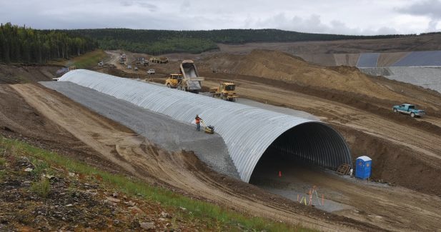
Figure 7. An engineered backfill zone and site soils for haul road grade separation. (Fort Knox Gold Mine; Fairbanks, Alaska)
Minimum cover and backfill zone width requirements are based on the structure geometry—specifically the ratio of crown radius to the haunch/side radius.
The crown is the top of the structure, and haunch/side is the portion of the structure immediately adjacent to the crown that will usually have a tighter radius of curvature.
- If the radius ratio is greater than 5:1, the minimum soil cover allowed is 2 feet, and the minimum backfill zone width is 1/5 of the structure span.
- If the radius ratio is less than 5:1, the minimum soil cover allowed is 3 feet, and the backfill zone width is 1/3 of the structure span.
For large-span structures, the minimum backfill zone width can be capped at 17 feet if the designer determines that width is acceptable based on the FEA results.
The cost and availability of suitable engineered backfill zone material varies widely based on project location, local geology, regional usage and other factors. This can be a significant or a minor cost and should be considered when evaluating structure options.
Foundation Considerations
Foundation costs are a significant consideration for both conventional and flexible buried bridge options. Flexible buried bridges have a much-higher differential settlement tolerance than most conventional bridges and rigid structures.
When the higher settlement tolerance is considered in the geotechnical analysis, a much-higher allowable bearing pressure often is possible, which can result in foundation cost savings or allow for use of spread footings when deep foundations otherwise would be needed.
The foundation-bearing elevation for buried bridges usually is much deeper than where a bridge sill would be located for a conventional bridge.
In many cases, this allows for buried bridges to bear directly on a stable foundation soil layer, rather than needing to extend foundations deeper, carry out a soil-improvement program or use deep foundations that might be needed for a conventional bridge.
It is important for the geotechnical engineer to consider foundation requirements for the buried bridge alternative differently than for the conventional bridge. In many cases, differences in foundation costs can be a significant deciding factor in the structure type.
Construction Considerations
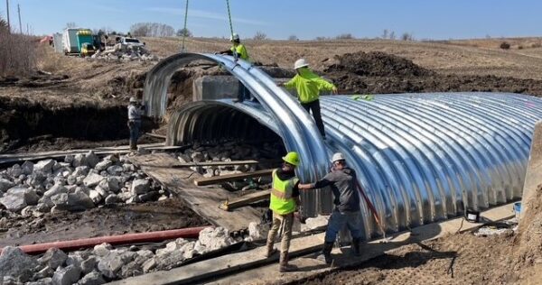
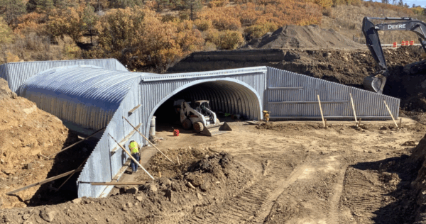
Construction costs and methods also should be considered and discussed with the manufacturer. Weights of individual plates typically are in the range of 350 to 1,200 pounds, depending on plate length and material thickness. This allows many structures to be assembled using a backhoe, forklift truck or other equipment already onsite for other work, keeping equipment costs down.
A crane typically is not required for assembly, and there is no need for specialized labor or heavy equipment—many counties and general contractors prefer to use their own equipment and labor forces whenever possible. The modular nature of flexible buried bridges makes them ideal for staged construction.
Part of the structure may be assembled and backfilled, and traffic put in service over the completed section while construction continues on the next. Depending on site limitations, a new buried bridge can be built below an existing bridge without taking it out of service.
Both scenarios (staged and in-place construction) can eliminate or significantly reduce the need for detours and traffic delays. Modular construction (where a buried bridge can be preassembled in large sections and set in place on the foundations) can be used in areas where only limited road closures are allowed.
Each project has its own unique set of construction requirements and challenges, and those should be considered for each structure type. There can be significant differences in the time and construction effort required among the options being considered.

Figure 8a. An assembly uses a backhoe (Attleboro, Mass., and Limon, Colo., respectively)

Figure 8b. An assembly uses a forklift truck. (Attleboro, Mass., and Limon, Colo., respectively)

Figure 9. A staged construction with 40-foot cover. (Washington DOT; Spokane, Wash.)
Conclusion
Flexible buried bridges can be an effective alternative to conventional bridges in many bridge applications.
Project-specific requirements, limitations and design challenges will impact the feasibility of a buried bridge alternative, while factors such as site conditions, foundation alternatives, construction considerations and overall project cost can provide valuable data points to help make the best decision on the better bridge type for the project.

Figure 10a. An in-place bridge replacement during construction (Missouri DOT; Lawrence County, Mo.)
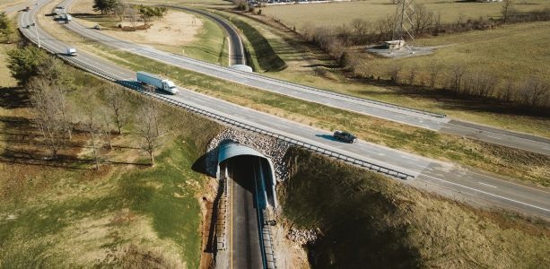
Figure 10. An in-place bridge replacement finished. (Missouri DOT; Lawrence County, Mo.)
Read Part 1 – Flexible Buried Bridges: dvantages and Applications (Part 1)
Author
Joel Hahm, P.E.
Contech Engineered Solutions
Joel.Hahm@ContechES.com
References
- AASHTO LRFD Bridge Design Specifications (9th Edition, 2020)
- AASHTO M145, Standard Specification for Classification of Soils and Soil-Aggregate Mixtures for Highway Construction Purposes
What are buried steel bridges?
Buried steel bridges provide an economical choices for bridge replacement or bridge rehabilitation.
They essentially are a corrugated steel pipe or structural plate pipe systems that is “buried” with backfill to carry loads through soil-structure interaction. This means the bridge structure itself and the backfill soils surrounding the structure interact with each other to support the loads. In effect, the backfill material is part of the bridge.
Because of this interaction, the bridge structure is typically lighter, and there can be significant savings in structure costs.
There are also many cases where buried bridges can carry heavier loads than traditional bridges because of the benefits of spreading vehicle loads through the fill. Buried bridges do not require abutments; and unless foundation soil conditions are poor, do not typically
require deep foundations.An additional benefit with buried bridges is that they can be tailored to site conditions and geometric requirements. The design includes inputs for site soils and backfill, meaning that locally available materials can often be used in construction and the structure can be tailored to fit the needs of the site and the owner’s requirements.
 Buried Bridge
Buried Steel Bridge Preserves Streambed While Supporting Heavy Loads
A new galvanized buried steel bridge in Riverside, Iowa, supplied by SSSBA member Lane Enterprises, replaced a weight-restricted structure and restored direct access for local farmers. Its open-bottom steel design preserves the natural streambed, enhances durability, and provides a cost-effective solution for rural infrastructure.
 Buried Bridge
Buried Steel Bridge Protects Wildlife and Motorists in New Mexico DOT Project
The New Mexico DOT buried steel bridge project, featuring SSSBA member Contech’s custom structural plate design, was honored as the NCSPA Project of the Year for its innovative wildlife crossing solution on I-25 at Raton Pass.
 Case Study
Steel in Action: On-Demand Steel Bridge Video Series
Watch this four-part, on-demand video series featuring expert-led case studies on cost-effective, resilient short span bridge projects—now available with downloadable presentation materials.
 News
News
NCSPA Announces 2025 Project of the Year Winners
The National Corrugated Steel Pipe Association announced the 2025 project of the year winners, including members of the Short Span Steel Bridge Alliance.
 Buried Bridge
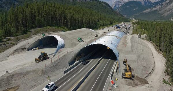
Corrugated Steel Animal Overpass Reduces Wildlife-Vehicle Collisions
The corrugated steel Stoney Nakoda Exshaw Wildlife Arch in Western Canada showcases the balance of engineering and environmental stewardship, setting a new standard for wildlife-friendly infrastructure.
 Buried Bridge
NCSPA Releases Report to Simplify the Seismic Design for Buried Structures
The National Corrugated Steel Pipe Association (NCSPA) released a groundbreaking report that simplifies the seismic design for buried structures including culverts, tunnels and buried steel bridges.